Understanding Optical Specifications-Geometric Specifications
Introduction:
The specifications of optics have significant impacts on the manufacturing and engineering of an optical component or an optical system since the optical specifications determine the production cost and performance. Therefore understanding the technical glossaries of Optical Specifications is of universal importance for either purchasing or fabricating all kinds of optics, ranging from optical windows, lenses, prisms, and mirrors, or polarizers, etc. Under-specification, where not all of the required parameters are defined appropriately, could lead to failure to achieve the designed functionalities. Over-specification, where the parameters are specified too tight, results in unnecessary cost rise and production hardship. Optical specifications can be divided into three subcategories, including Geometric Optical Specifications, which are the optical specifications related to the geometric shapes of the optics, Surface Optical Specifications, which are the optical specifications related to the surface metrological parameters, and Material Optical Specifications/Properteis, which are the optical specifications related to the material properties of the optics. In this article, we will delve into the domain of geometric specifications, and as for the surface and material specifications we will discuss them in two other forthcoming articles, you can bookmark our resource center and follow our updates.
We have also produced new content introducing surface optical specifications and optical material properties, you can click on the bold text to learn more if you are interested.
We have also overhauled our company homepages on Linkedin and Facebook, in our public channels, we will publish our latest company news, activities, released products, blogs about our technical insights and analysis, professional experiences, and videos showing the fabrication/inspection procedures in our factories&labs and more. We will also share lots of useful tips and application notes for handling optical components and assemblies. Click on the links below to subscribe to Shalom EO’s company homepage, welcome to join the discussion on our public channels, we are keen to get comments and inspirations from you!
In this article learn about the concepts and regular standards of following glossaries in geometric optical specifications:
These crucial parameters regulate the deviation of the optics from its designed geometric shapes, thus having great influences on the optical aberrations. Proper specifications ensure adequate performance and rational costs.
- Dimensional Tolerance
- Center Thickness Tolerance
- Angle Tolerance
- Centering Error
- Radius of Curvature
- Clear Aperture
- Bevel
- Parallelism
- Angle of Incidence (AOI)
The Precision Standards of Specifications:
Normal: The normal standard products are the most conventionally available factories with minor or little production difficulties. These products also tend to have lower production costs than the other two standards.
Precise: Necessitates certain production capabilities, but is still procurable in most factories. It might bring a substantial percentage of cost increase.
High Precision: Necessitates sophisticated facilities and techniques. Premium costs.
Dimensional/Diameter Tolerance:
Dimensional tolerance refers to the permissible deviation from specified diameter/dimensions in optical components. It ensures that the dimensions of lenses, mirrors, and other optical elements remain within acceptable limits. It is worth noting that albeit the diameter tolerance does not affect the performance of the optics itself, the mechanical tolerance needs to be taken into consideration if the optical components are to be mounted on holders. For example, discrepancies in the diameter from its nominal value will cause misalignment between the mechanical axis and the optical axis in the mounted optics, the consequence is decenter.
The Table for Precision Standards of Dimensional Tolerance:

Center Thickness Tolerance:
Center thickness tolerance specifies the allowable deviation from the nominal value of thickness measured at the center of an optical component, such as a lens or a prism. This parameter is critical for maintaining optical performance, in particular in systems where precise focal lengths or optical path lengths are crucial. This is because the center thickness, in combination with the radius of curvature, defines the path length.
The Table for Precision Standards of Center Thickness Tolerance:


Figure 1. shows the center thickness of a plano convex lens from Shalom EO
Angle Tolerance:
Angle tolerance is majorly utilized for optical components consisting of non-parallel surfaces, such as prisms or beamsplitters. Angle tolerance defines the permissible deviation of the angles between the adjacent surfaces from its nominal value. Angle tolerance is often measured in arcminutes or arcseconds. It ensures that the angles between the surfaces that are crucial for light manipulation, reflection, or refraction remain within acceptable limits, preventing aberrations and safeguarding optical performance.
The Table for Precision Standards of Angle Tolerance:

Centering Error:
Centering error, also called decenter or centration quantifies the departure of the optical axis from the mechanical axis of a lens. The mechanical axis is identical to the geometric axis of the lens and is and is defined by the ground edge of the lens. The optical axis is the line connecting the two centers of curvatures of the surfaces. Precise centering is essential for maintaining optical alignment and minimizing optical aberrations, especially in complex optical systems comprising multiple elements.
Radius of Curvature:
Radius of curvature is the distance of the vertex of the optics to the center of curvature. Given this value, one can deduce the optical path length of light traveling through the optical components and it also instrumental in determining the the power of the surface. Precise control of the radius of curvature ensures optical components meet design specifications and perform with optimal competence.
The Table for Precision Standards of Radius of Curvature:

Clear Aperture:
Clear aperture (CA) is the diameter of the area or a specific proportion of the optic within which the specifications are valid. Outside the area of the clear aperture, the manufacturer does not guarantee all the published specifications are met. It is almost unfeasible for manufacturers to make the clear apertures equal to the diameters (or lengths) of the optical components due to fabrication restrictions.
Common Clear Aperture Values against Diameter

Bevel:
Bevel refers to the chamfered faces between the edges or corners of an optical component. It is often applied to prevent brittle materials like glass from chipping, which can be problematic in the polishing/lapping procedure and facilitate handling during the assembling procedure. A bevel is defined by a cut angle and a face width. The most regular cut angle is 45°, and the maximum face width allowed to be made varies depending on the dimensions of the optics. Another important concern is that bevels are not requisite for small radii of curvature.
The Table of Maximum Face Width of Bevel against Diameter

Parallelism:
Parallelism measures how parallel two surfaces are. Parallelism is utilized for optics with parallel planes (e.g. windows, polarizers) where deviation from the parallel relationship between the surfaces of optics can lead to distortion and beam divergence, which brings adverse impacts on image and light quality.
Angle of Incidence (AOI):
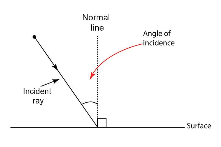
Angle of incidence (AOI) denotes the angle or range of angles within which the optical component is engineered to receive light. It represents the angle at which you can anticipate the specified optical performance of the optical component to remain effective. The AOI is the angle formed between the normal incidence angle (0°, a theoretical line perpendicular to the surface of the component at the optical axis) and the incident Light irradiated from the light source and hitting the surface of an optic.

Figure 2 shows the angle of incidence
How to Read Optical Specifications
Reading and interpreting optical specifications involves understanding the relevant optics terms and their explanations. Here’s a quick guide:
- Refer to the Optical Specification Glossary: Use an optical specification glossary to understand the definitions of terms.
- Evaluate the Parameters: Assess the given parameters against the required performance criteria for your application.
- Consult Standards: Check industry standards such as ISO or MIL-PRF for detailed definitions and acceptable tolerances.
- By mastering these optics concepts, you can ensure that the optical components you design, manufacture, or purchase meet the necessary performance requirements.
Hangzhou Shalom EO’s Metrology
Understanding optical specifications is fundamental for anyone involved in the optics field. This article has provided a detailed explanation of surface specifications, including surface quality, flatness, roughness, power, irregularity, and fractures/chips. These parameters are crucial for the performance and functionality of optical components.


Tests using Zygo interferometer and microscope in Shalom EO
Hangzhou Shalom EO has a matured ISO 9001-certified quality control system. In our Class 100000 Cleanroom inspection lab, all the products will undergo stringent supervision before dispatch to ensure the actual parameters of products meet or exceed the published specifications.
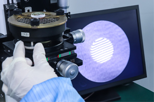
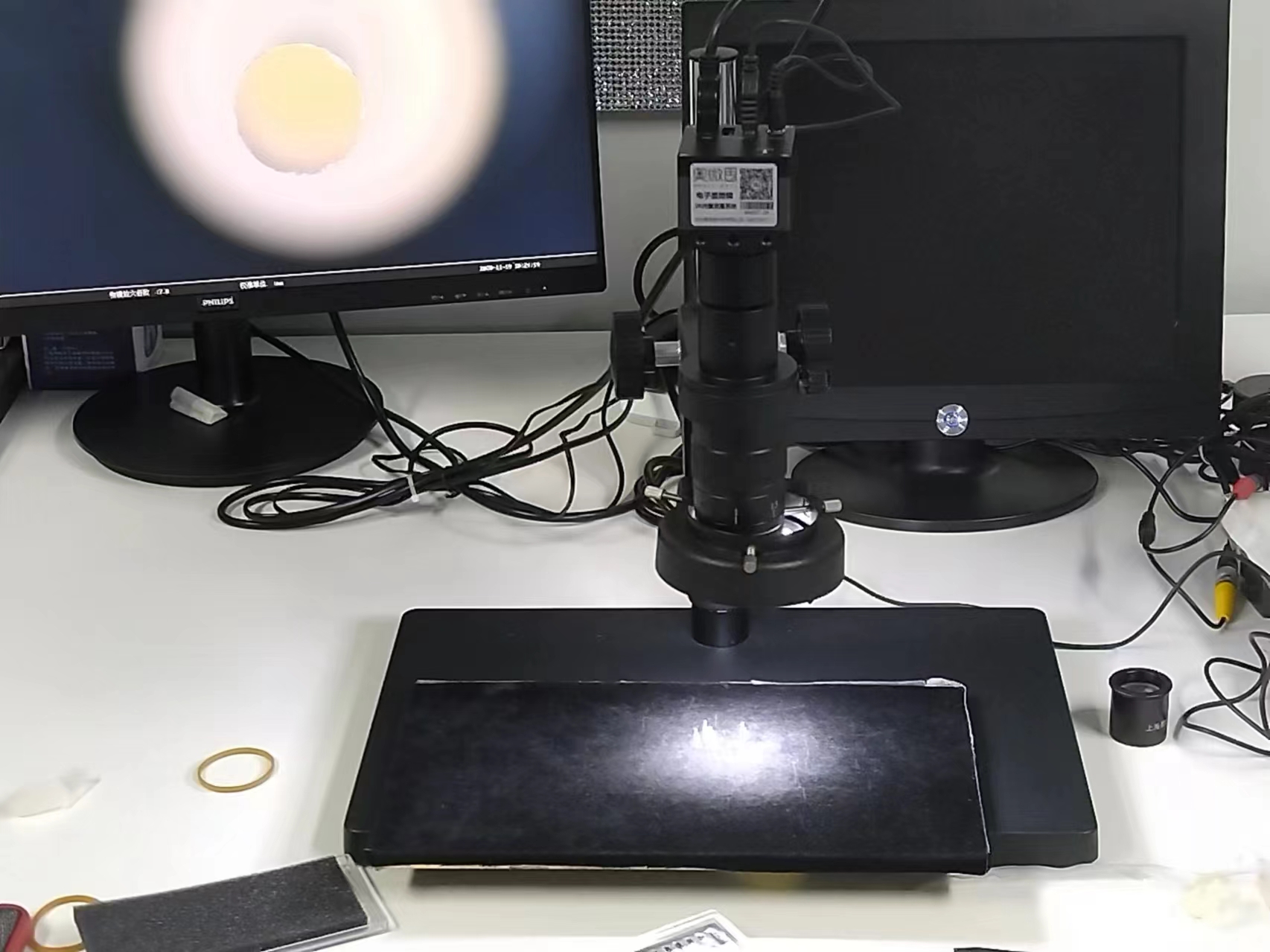
For the visual error, the scratches/digs are identified by qualified personnel with developed skills and trained experiences, under the observation of an intense light source with a 10x microscope.
The dimensions of the product are measured using vernier calipers and micrometer screws to ensure the actual dimension remains within the required tolerances. The vernier calipers and micrometer screws are calibrated on a routine basis so that the equipment stays correct.
For the surface flatness errors, power, and parallelism, reliable equipment--Zygo interferometer is utilized.
An atomic force microscope is utilized to obtain authentic measurements of the surface roughness.
Tags: A Guide to Optical Specifications


